Most slow and unstable networks share one root cause: they were never designed, they grew bit by bit as users were added. Every time a user was added, another switch was hung off the previous one, and after a few years what is left is a network nobody has an accurate map of. The three-tier model is the standard way to design an enterprise network, making it predictable, scalable and easy to troubleshoot.
The three layers and the role of each
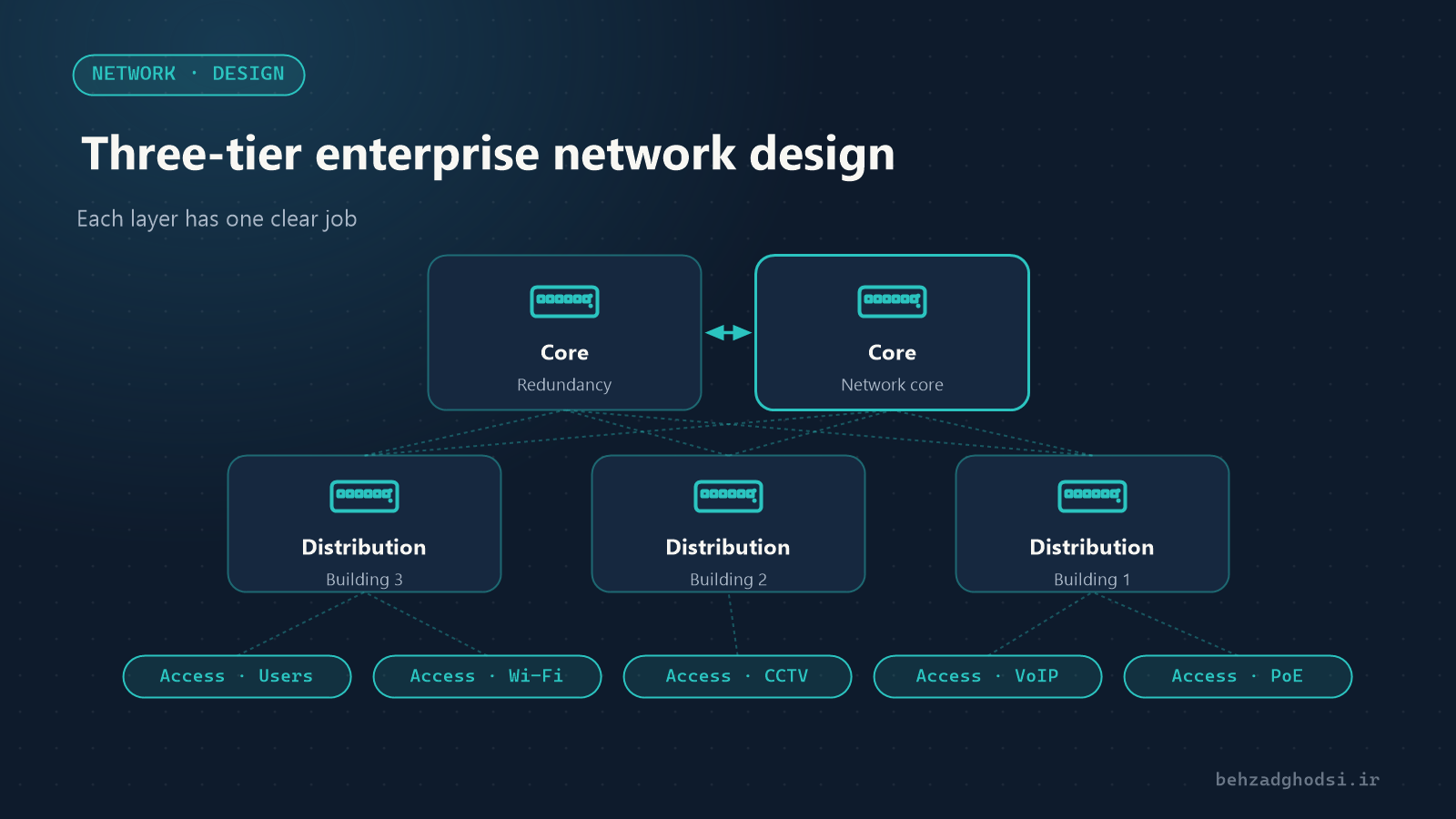
The Access layer
Where users and devices connect to the network: computers, VoIP phones, cameras, access points and printers.
- Access switches usually sit on each floor or in each hall.
- PoE for phones, cameras and access points is needed at this layer.
- Each port is placed in its proper VLAN, and port security (such as Port Security and BPDU Guard) is applied here.
The Distribution layer
The access switches of each building or department connect to the distribution layer.
- Routing between VLANs usually happens at this layer.
- Policies and filters (ACLs) and control of traffic between departments live here.
- Each access switch should ideally connect to distribution with two links.
The Core layer
The backbone of the network, connecting the distribution switches and the data centre.
- Its only job is fast, reliable forwarding of traffic; do not put filtering or extra processing in the core.
- It must be redundant, usually two core switches, so the failure of one does not stop the network.
The two-tier model for smaller networks
In small and medium organisations, the core and distribution layers are often combined in one pair of switches (collapsed core). This model is enough for a single building with a few hundred users and keeps costs down. Once the number of buildings or distribution switches grows, a separate core makes sense.
Separating traffic with VLANs
A flat network, with every device in one VLAN, has two big problems: too much broadcast traffic and weak security, since one infected device can reach everything. A simple, practical plan:
- Office users
- Servers
- VoIP phones
- CCTV cameras
- Staff Wi-Fi and guest Wi-Fi (kept apart)
- Device management (for the network administrator only)
VLAN configuration on Cisco switches is covered in Configuring VLANs and a VTP server on Cisco switches.
Redundancy and removing single points of failure
- Two links from each layer to the layer above, with EtherChannel or routing, so a cut cable does not stop the network.
- Two switches in the core or collapsed core.
- Configure Spanning Tree deliberately: choose the root bridge yourself, on the core or distribution, rather than leaving it to the switches’ random election.
- For the gateway, use methods such as HSRP or VRRP, so the failure of one switch does not take away the users’ gateway.
Example: a multi-building factory
- The data centre in the office building, with two core switches and the servers.
- Each building (production hall, warehouse, office building) has a distribution switch connected to the core over fibre.
- Remote buildings where fibre is not cost-effective are connected with a wireless link. Compare the two methods in Fibre or wireless link.
- PoE access switches in each hall for computers, phones, cameras and access points.
See a real example of such a design in the steel raw-materials plant case study.
Documentation: part of the design, not an afterthought
A network that is not documented is effectively locked when one person leaves. The minimum documentation:
- The logical map (VLANs, addressing, routes) and the physical map (racks, cables, ports)
- The IP addressing and VLAN table
- The equipment list, with model, software version and location
- Configuration backups of every switch and router
Common design mistakes
- Daisy-chaining switches instead of connecting them in a star to the layer above
- Every device in one VLAN
- One link and one switch for the whole network, which means a single point of failure
- Buying access switches without enough PoE budget for phones and cameras
- Starting the installation without a map and an addressing table
The three-tier model gives each layer one clear job: access for connecting, distribution for policy and routing, core for fast forwarding. With proper VLANs, redundancy in the upper layers and complete documentation, the network does not slow down as the organisation grows and stays easy to troubleshoot.
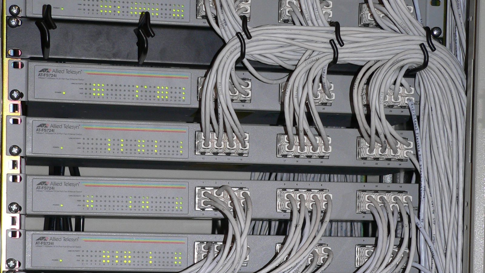
Photo at the top of the article: Parkis, licensed under CC BY-SA 3.0, via Wikimedia Commons; cropped.