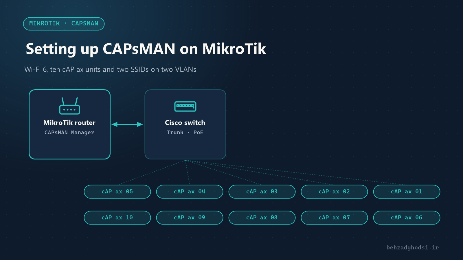
When a building has several access points, configuring each one separately is both slow and error-prone. CAPsMAN (Controlled Access Point system Manager) is MikroTik’s centralised wireless management: every access point takes its configuration from one router, the SSID and password are changed in one place, and users move between access points without losing their connection.
In this article we set up CAPsMAN for 10 cAP ax units (Wi-Fi 6) on RouterOS 7 and create two SSIDs: one for staff and one for guests. Each SSID’s traffic travels on a separate VLAN from the MikroTik router, through a Cisco switch, to the access points, so guests have no way into the internal network.
Important: old CAPsMAN or new?
MikroTik has two CAPsMANs, and this is where most mistakes happen:
- The old CAPsMAN (the
/caps-manmenu): for older Wi-Fi 4 and 5 devices with the wireless driver. - The new CAPsMAN (the
/interface wifi capsmanmenu): for newer devices with the wifi driver, including every Wi-Fi 6 device such as the cAP ax.
The cAP ax can only be managed by the new CAPsMAN. The /caps-man commands in older tutorials do not apply to it.
The scenario and VLAN plan
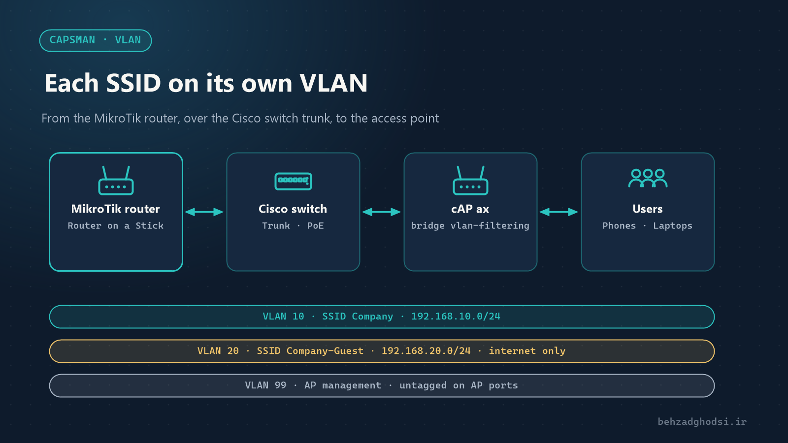
- MikroTik router (for example an RB5009 or a CCR with RouterOS 7): the CAPsMAN manager, and the gateway and DHCP server for all three VLANs. Port
ether1goes to the internet and portether2to the Cisco switch. - Cisco PoE switch (Catalyst series): port
Gi1/0/1to the router and portsGi1/0/2toGi1/0/11to the ten cAP ax units. - 10 cAP ax units, powered from the PoE switch.
There are three VLANs:
- VLAN 10 (staff): SSID
Company, network192.168.10.0/24 - VLAN 20 (guest): SSID
Company-Guest, network192.168.20.0/24, internet access only - VLAN 99 (access point management): network
192.168.99.0/24; the cAP ax units get their addresses here and talk to CAPsMAN
On the access point ports, VLAN 99 passes untagged (native) and VLANs 10 and 20 pass tagged. All devices should run the same RouterOS 7 version, and the cAP ax units need the wifi-qcom package.
Part one: VLANs on the MikroTik router
The router works as a router on a stick: three VLAN interfaces on ether2, which connects to the Cisco switch trunk.
1. VLAN interfaces and addresses
/interface vlan add name=vlan10-staff interface=ether2 vlan-id=10
/interface vlan add name=vlan20-guest interface=ether2 vlan-id=20
/interface vlan add name=vlan99-mgmt interface=ether2 vlan-id=99
/ip address add address=192.168.10.1/24 interface=vlan10-staff
/ip address add address=192.168.20.1/24 interface=vlan20-guest
/ip address add address=192.168.99.1/24 interface=vlan99-mgmt
If ether2 is a member of the default bridge, remove it from the bridge first.
2. DHCP for each VLAN
/ip pool add name=pool-staff ranges=192.168.10.100-192.168.10.250
/ip pool add name=pool-guest ranges=192.168.20.100-192.168.20.250
/ip pool add name=pool-mgmt ranges=192.168.99.100-192.168.99.150
/ip dhcp-server add name=dhcp-staff interface=vlan10-staff address-pool=pool-staff
/ip dhcp-server add name=dhcp-guest interface=vlan20-guest address-pool=pool-guest lease-time=2h
/ip dhcp-server add name=dhcp-mgmt interface=vlan99-mgmt address-pool=pool-mgmt
/ip dhcp-server network add address=192.168.10.0/24 gateway=192.168.10.1 dns-server=192.168.10.1
/ip dhcp-server network add address=192.168.20.0/24 gateway=192.168.20.1 dns-server=192.168.20.1
/ip dhcp-server network add address=192.168.99.0/24 gateway=192.168.99.1 dns-server=192.168.99.1
More DHCP details are in Setting up a DHCP server on MikroTik.
3. Isolating guests with the firewall
Guests should only reach the internet, with no access to the internal networks or the router itself (except DNS and DHCP). Place these rules above the general accept rules:
/ip firewall filter add chain=input in-interface=vlan20-guest protocol=udp dst-port=53,67 action=accept comment="Guest: DNS and DHCP"
/ip firewall filter add chain=input in-interface=vlan20-guest protocol=tcp dst-port=53 action=accept comment="Guest: DNS over TCP"
/ip firewall filter add chain=input in-interface=vlan20-guest action=drop comment="Guest: no access to router"
/ip firewall filter add chain=forward in-interface=vlan20-guest out-interface=!ether1 action=drop comment="Guest: internet only"
A masquerade rule on ether1 (internet) is enough for all three VLANs.
Part two: the Cisco switch
1. Create the VLANs
vlan 10
 name STAFF
vlan 20
 name GUEST
vlan 99
 name AP-MGMT
2. The router port (trunk)
interface GigabitEthernet1/0/1
 description Uplink to MikroTik
 switchport mode trunk
 switchport trunk allowed vlan 10,20,99
3. The access point ports
VLAN 99 untagged (native) for managing the cAP ax, and VLANs 10 and 20 tagged for the two SSIDs:
interface range GigabitEthernet1/0/2 - 11
 description cAP ax
 switchport mode trunk
 switchport trunk native vlan 99
 switchport trunk allowed vlan 10,20,99
 spanning-tree portfast trunk
 power inline auto
On some older Catalyst models you also need switchport trunk encapsulation dot1q before switchport mode trunk.
Put the staff’s wired computer ports in VLAN 10 as access ports:
interface range GigabitEthernet1/0/12 - 24
 switchport mode access
 switchport access vlan 10
 spanning-tree portfast
Finally run write memory.
Part three: CAPsMAN configuration on the router
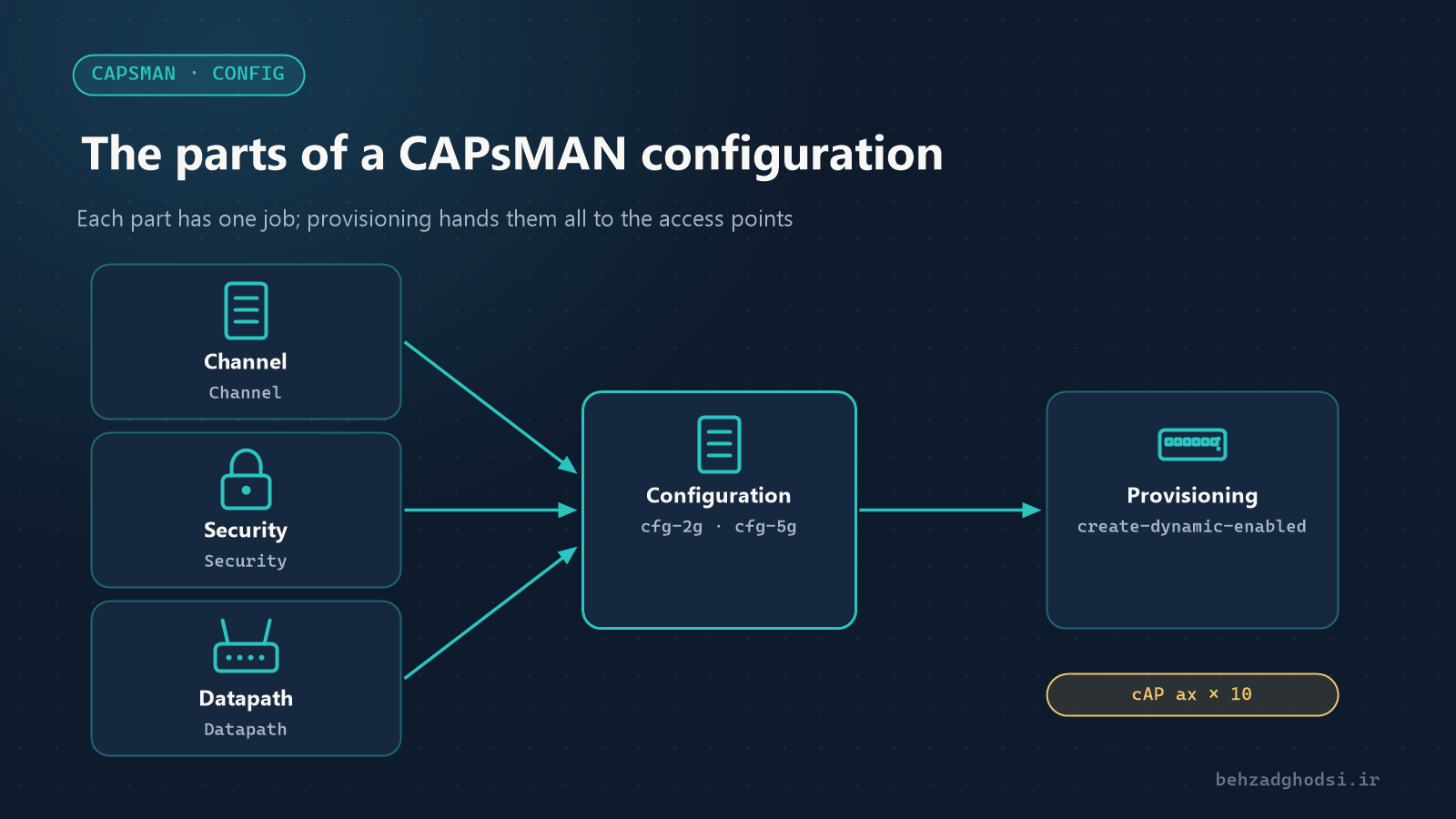
All of the settings below are also available in Winbox under the WiFi menu, on the Channels, Security, Datapath, Configurations, Provisioning and CAPsMAN tabs.
1. Channel profiles
/interface wifi channel add name=ch-2g band=2ghz-ax width=20mhz frequency=2412,2437,2462
/interface wifi channel add name=ch-5g band=5ghz-ax width=20/40mhz- In 2.4 GHz allow only channels 1, 6 and 11; these three do not overlap.
- In 5 GHz, with 10 access points in one building, a 40 MHz width is usually better than 80.
2. Two security profiles
/interface wifi security add name=sec-staff authentication-types=wpa2-psk,wpa3-psk passphrase="Str0ng-Staff-Pass" ft=yes ft-over-ds=yes
/interface wifi security add name=sec-guest authentication-types=wpa2-psk,wpa3-psk passphrase="Guest-WiFi-Pass"
ft=yes enables 802.11r so staff roam quickly between access points. Choose long passphrases and do not use this article’s examples.
3. Two datapaths: each SSID on its own VLAN
This is the most important setting in this part: the datapath decides which VLAN ID each SSID’s traffic leaves the access point with.
/interface wifi datapath add name=dp-staff bridge=bridge vlan-id=10
/interface wifi datapath add name=dp-guest bridge=bridge vlan-id=20
bridge is the bridge name on the cAP ax (part four). Traffic is forwarded locally from the access point, tagged with its VLAN, into the switch, and goes through the router as that VLAN’s gateway.
4. Configurations
Two main configurations for the staff SSID (one per band) and one for the guest SSID:
/interface wifi configuration add name=cfg-staff-2g ssid="Company" country="United Kingdom" channel=ch-2g security=sec-staff datapath=dp-staff
/interface wifi configuration add name=cfg-staff-5g ssid="Company" country="United Kingdom" channel=ch-5g security=sec-staff datapath=dp-staff
/interface wifi configuration add name=cfg-guest ssid="Company-Guest" security=sec-guest datapath=dp-guest
Set country to the country where the devices are installed; the allowed channels and transmit power are based on it. Press Tab in the terminal to see the exact country name.
5. Enable CAPsMAN
/interface wifi capsman set enabled=yes interfaces=vlan99-mgmt upgrade-policy=suggest-same-versionCAPsMAN only answers access points on the management network (VLAN 99), not on the staff or guest networks.
6. Provisioning
The staff SSID as the master and the guest SSID as a slave (a second virtual interface on the same radio):
/interface wifi provisioning add action=create-dynamic-enabled supported-bands=2ghz-ax master-configuration=cfg-staff-2g slave-configurations=cfg-guest
/interface wifi provisioning add action=create-dynamic-enabled supported-bands=5ghz-ax master-configuration=cfg-staff-5g slave-configurations=cfg-guest
With these two rules, every cAP ax that joins the network automatically broadcasts both SSIDs on both bands.
Part four: preparing the cAP ax units
All 10 units must be in CAP mode, and their bridge must have VLAN filtering so the two SSIDs’ traffic reaches the switch with the right tags. Do this in Winbox (connecting by MAC) or over a console cable; enabling VLAN filtering may briefly drop the IP connection.
/interface bridge add name=bridge vlan-filtering=yes
/interface bridge port add bridge=bridge interface=ether1
/interface bridge vlan add bridge=bridge vlan-ids=10,20 tagged=ether1
/ip dhcp-client add interface=bridge
/interface wifi cap set enabled=yes discovery-interfaces=bridge
/system identity set name=cap-floor1-01ether1is the port connected to the Cisco switch.- Untagged traffic on the port (VLAN 99 on the switch) is for the device itself; the cAP ax gets an address by DHCP from
192.168.99.0/24and finds CAPsMAN. - VLANs 10 and 20 are allowed tagged on
ether1, and the radios join this bridge with the VLAN ID set in the datapath. - Give each unit a clear name so it can be identified in the CAPsMAN list.
If the units have the default configuration and the address 192.168.88.1, reset them one by one before connecting them to the main network, so you do not end up with several DHCP servers on the network.
Part five: verification
On the router:
/interface wifi capsman remote-cap print
/interface wifi print
/interface wifi registration-table print
/ip dhcp-server lease printremote-capshould list 10 units with the statusOk.- Four dynamic interfaces are created for each unit: two radios, each with two SSIDs.
- A phone on
Companyshould get a192.168.10.xaddress, and a phone onCompany-Guesta192.168.20.xaddress.
On the Cisco switch:
show vlan brief
show interfaces trunk
show power inline
show interfaces trunk should list ports Gi1/0/1 to Gi1/0/11 with VLANs 10, 20 and 99, and show power inline should show power delivered to every cAP ax.
Finally, from a phone on the guest network, ping 192.168.10.1; it must not answer, but the internet must work.
Channel and power planning for 10 access points
- Turn the power down. Full power makes phones cling to a distant access point and roam late. Set
tx-powerin the configuration below the maximum and test on site. - Neighbouring access points should not share a channel. If automatic selection does not give good results, set a fixed channel for each access point.
- Do not add many SSIDs. Each extra SSID adds management overhead on every radio; two SSIDs are enough for most organisations.
- Placement matters more than settings: do not put access points behind concrete pillars, inside metal false ceilings or next to the rack.
Troubleshooting
- The cAP ax does not appear in remote-cap: the Cisco port’s native VLAN is not 99, DHCP is not working on
vlan99-mgmt, or CAPsMAN is enabled on another interface. - The SSID is visible but users get no address: the VLAN is missing from
switchport trunk allowed vlanon the access point port or the router port, orether1is not tagged in the cAP axbridge vlantable. - Staff users get guest addresses, or vice versa: the
vlan-idvalues of the two datapaths are swapped. - Guests can reach the internal network: the guest firewall rules sit below the accept rules; fix the order.
- The connection to the cAP dropped after enabling VLAN filtering: connect with Winbox by MAC and check the
bridge vlantable. - Commands give errors: you used the old
/caps-manmenu, or the RouterOS version is old.
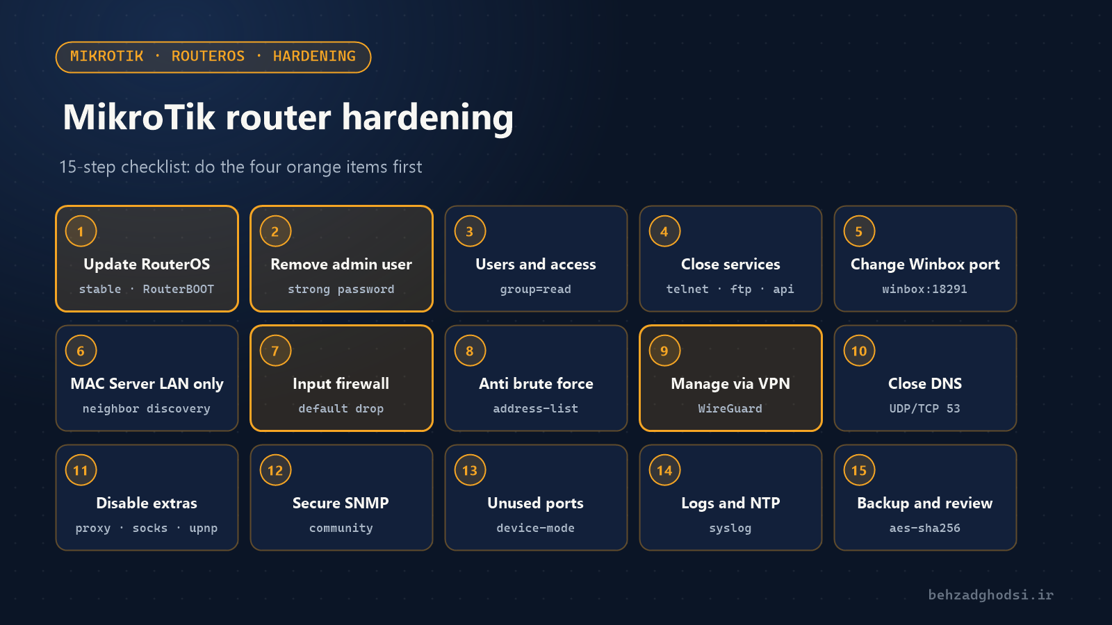
With the new CAPsMAN, ten cAP ax units are managed in one place, and the staff and guest SSIDs, each on its own VLAN, stay separated from the access point through the Cisco switch to the MikroTik router. Three things must match: the vlan-id in the datapath, the allowed VLANs on the Cisco trunk and VLAN filtering on the cAP ax bridge. See examples of central MikroTik Wi-Fi in the Golrokh Teb imaging centre and Energy Gostaran Mottahed building projects. For VLANs on Cisco switches, read Configuring VLANs and a VTP server on Cisco switches, and for router hardening, Network security with MikroTik.